
Case Study
Strong motion monitoring, Angeghakot Dam, Armenia
01 June 2021
Armenia
Summary details
Vorotan Cascade (ContourGlobal Hydro Cascade)
Country: Armenia, Syunik Province
Construction: Began in 1961
Purpose: Hydropower and irrigation reservoirs
Owner: ContourGlobal since 2015
Cascade: 3 Hydro Power Plants (HPP) and 5 reservoirs
Cascade head: 1123 m total
Installed capacity: 404.2 MW, average power generation of 1.15GWh annually
Angeghakot dam reservoir
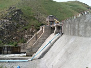
Type of dam: Concrete spillway dam
Height: 23.4 m
Capacity: 3‘400‘000 m3
Highest water level: 1‘677.4 m a.s.l (above sea level)
Lowest water level: 1‘664.5 m a.s.l
Introduction
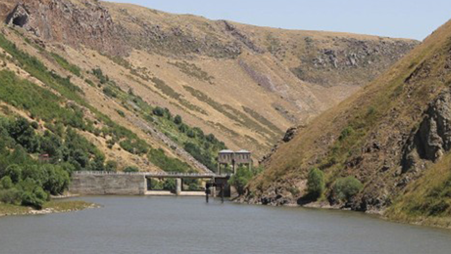
This case study highlights the strong motion instrumentation of the Angeghakot dam reservoir, situated in a high seismic hazard region of Armenia. A seismic monitoring system is installed on the dam for structural monitoring and safety measures. The installation was conducted during Q2-2021 and it is now fully operational.
This specific dam is part of the Vorotan Cascade. A major refurbishment program lasting at least 6 years was undertaken since 2015 in order to modernize the HPP and improve the operational performance, safety, reliability and efficiency of the whole cascade.
SHA - Seismic Hazard Analysis map
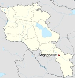
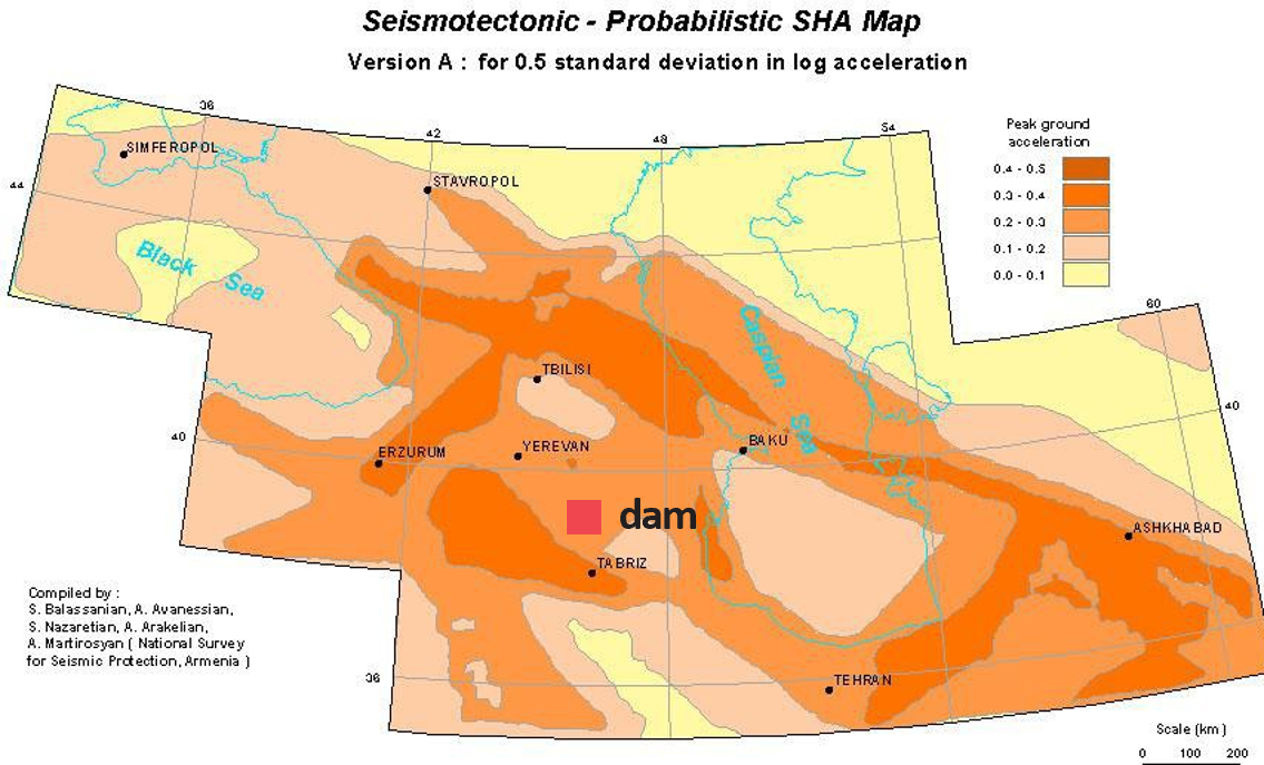
The Angeghakot dam is located within a triangle formed by Yerevan, Tabriz, and Baku; refer to Figure 2. In this Caucasus region, a probabilistic map of PGA - Peak Ground Acceleration expected with a 10% exceedance probability in 50 years (return period of 475 years) is computed and displayed.
The PGA is expected to be between 0.2 and 0.3 g at the present dam location.
|  |
 |
Monitoring setup
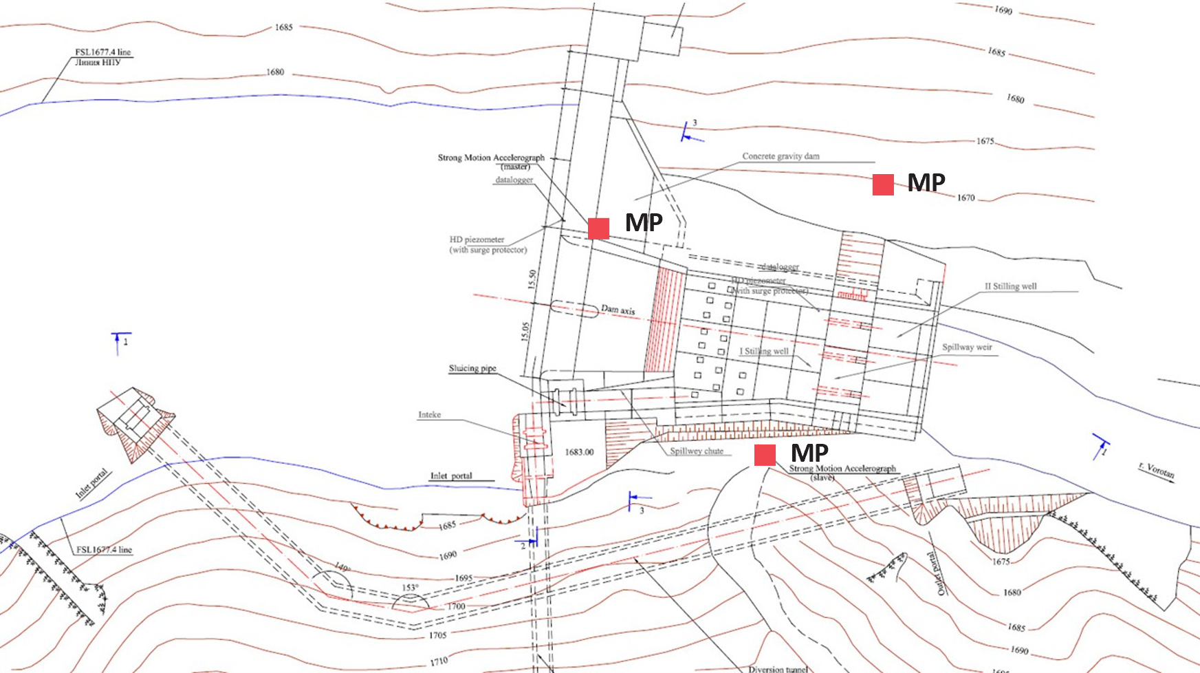
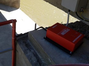
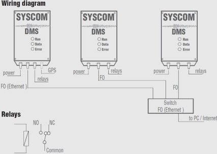
The dam is equipped with 3 SYSCOM MR3000DMS - dam monitoring system for strong motion monitoring . These devices are interconnected and synchronised using fibre optics in a LAN network. The distributed architecture is a key aspect of the instrumentation, providing the best reliability, remaining operational in case of network or single component failure.
One of the LAN network's purposes is to be able to configure alarm voting logic, typically in a 2/3 (2 out of 3) logic in this case, enabling the highest confidence in alarming raised by the automated system. The voting logic is also key to ensuring no false activation of the system in the event of a spurious event (for example, during maintenance) detected by a single device.
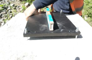
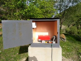
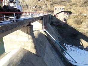
The devices are protected against external conditions by cabinets and properly grounded. In order to measure the ground/structure motion without alteration, a concrete pedestal is built on-site, especially for the free-field location, as displayed on Figure 6.
The MPx (Measuring Points) in Figure 3, refers to:
- MP1: master device on the dam concrete structure
- MP2: slave device on rock soil - structure interaction
- MP3: slave device as free field for input motion monitoring.
 |  |
 |  |
 |
Instrumentation
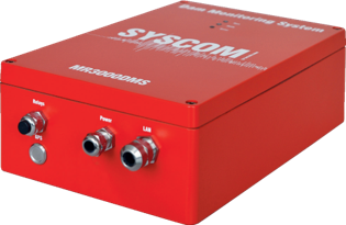
Syscom MR3000DMS are tailored for dam structural health monitoring. It integrates, in a unique housing, all the required features of the most advanced accelerographs for optimal communication capabilities, reliability, and ease of installation.
The use of MEMS sensing technology also achieves the lowest cost of ownership for the monitoring system, as it requires no periodic calibration. In addition, the MR3000DMS device's continuous auto-test feature will instantly alert the owner to any system issue.
Main characteristics of MR3000DMS devices:
- ± 4 g triaxial acceleration sensor
- 24 bits A/D converters and WebUI for easy setup
- OVP - Over Voltage Protection, type I & II
- Fiber optics communication
- GPS time synchronization
- Industrial cable glands and internal terminals (no additional junction box needed).
|
Refer to MR3000DMS datasheet for the complete specifications.
Typical 3-device wiring diagram, using fibre optics, fully protected against lightning surge, in a star network architecture.
The distributed intelligence system provides the best reliability, and the MR3000DMS relays' output can automatically and instantly trigger on-site safety actions post-earthquake.
The seismic system alarm can be configured based on OBE (Operating Basis Earthquake), SSE (Safe Shutdown Earthquake), and RSP (Response Spectrum).
 |
Conclusion
The Angeghakot dam, part of the Vorotan Cascade, is now continuously monitored, and its structural response will be recorded during the next earthquake-induced ground motion. This will provide critical insights for SHM - Structural Health Monitoring and safety assessment of the reservoir over time.
We are grateful to our partner Hydro Solutions LLC for allowing us to write this case study: http://hydrosolutions.am/
- END -