Insight
Coherence Attribute Measurement – A New Approach to Detecting Imminent Slope Failure
08 May 2020
GroundProbe's Regional Geotechnical Manager - Asia, Rachmat Hamid Musa
GroundProbe's Senior Geotechnical Engineer, Rahardian Dwitya
Detecting an imminent failure is immensely important in slope stability monitoring, especially in open pit mining where potential hazards can significantly impact safety and production. The current, well-accepted method for detecting imminent failure is to monitor slope behaviour and make predictions based on the interpretation of progressive slope deformation. However, a new approach – using the coherence attribute produced by ground-based slope radar – helps to ensure detection of imminent failure, support existing detection methods and deliver more precise results.
Radar Interferometry for Slope Monitoring
Interferometry – a method to extract information from the ‘interference phenomenon’ of electromagnetic waves – has long been incorporated into ground-based slope radar. Ground-based slope radar methodology combines the concept of measuring minute deformation using interferometry with the flexibility of its ground-based deployment. Interpretation of the deformation behaviour from ground-based slope radar provides subtle information for slope stability monitoring. Extensive research into mining wall rock has shown that before a rock mass failure occurs, small precursor movements in the rock wall appear over extended periods. Observing the deformation behaviour preceding the failure event could provide insight into future failure detection and prediction.
Amplitude, Range and Coherence Value
Coherence measurement in ground-based slope radar is inherently related to both amplitude and range, with amplitude signifying the strength of the returned signal from the observed object and range signifying the distance between the radar and the observed object.
The coherence value of ground-based slope radar reveals the consistency of amplitude and range. The scale of coherence value is from a maximum of one to a minimum of zero:
- Coherence value equal to one means that the surface of the area monitored is intact and undisturbed.
- Any disturbance will be expressed by drop in coherence value below 1.
Coherence implies the normalised complex cross-correlation function of amplitude and range measurements. If the comparison between amplitude signatures and the distance of the wall or object from ground-based slope radar in successive scan exhibit a degree of difference, the ground-based slope radar system will yield a low coherence value.
A shift in coherence value will tell whether the surface of a slope is changing or not – and can indicate an impending failure.
Detecting Impending Failure Using Coherence Value
The Coherence Shifting Method
To understand the role of coherence value in failure detection, it is important to recognise the nature of coherence value shifting when a wall is approaching a failure event.
Detecting failure by simply observing drops in the coherence value of each radar pixel will be ineffective, as a significant drop in coherence doesn’t happen in a progressive fashion While failure events will commonly coincide with a drop of coherence value from, for example, above 0.95 to below 0.2, this deflation can happen on average after only two to three radar scans – and in many instances leave insufficient time to mitigate an impending failure.
Rather than assigning a certain parameter based on the deflation of coherence value, the method being conveyed will benefit from the sensitivity of coherence reading conducted by ground-based slope radar. The method of detecting impending failure using coherence is best explained by creating coherence imagery – where the coherence value of each single pixel is representation by colour gradient, depending on the threshold parameter set. By default, a high coherence value and will be represented by a lighter colour while a low value will be represented by a darker colour. Based on this method, an impending failure can be visibly detected by observing this coherence shifting phenomenon – known as the coherence shifting method.
Case Study One – Coal Mining with Soft Rock Type
Case study one demonstrates a sequence of failures taking place at a coal mine where the slope wall is a soft rock type. The progressive deformation behaviour, exhibited in a cluster of 120 pixels, had been clearly emerging from the start of the radar scanning period. This case shows a clear gradation of coherence image shifting from quite early in the radar scan. The changing tone of the coherence image from light to dark happened quite haphazardly, presumably because the mechanism of the failure belongs to the creep failure mechanism (Figure 1 and 2).
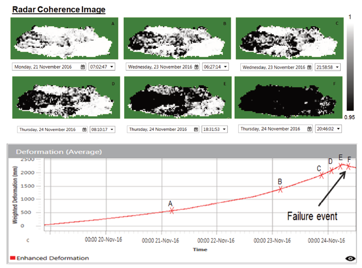
Figure 1: Coherence shifting image from ground-based radar
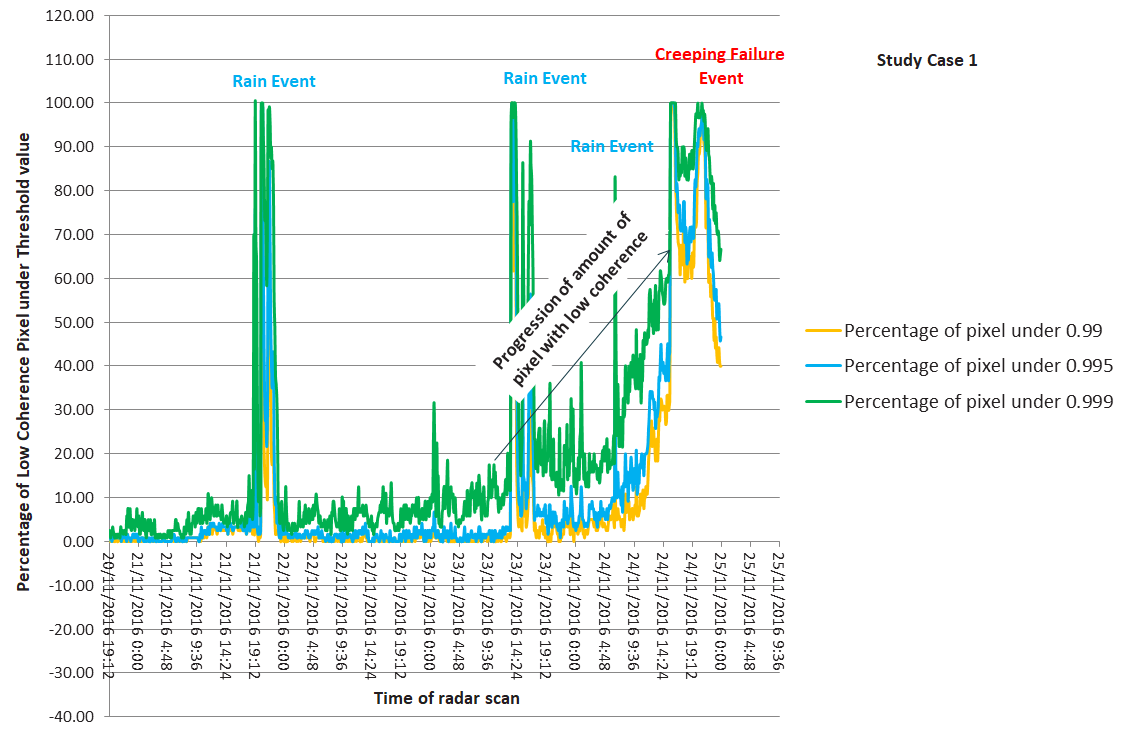
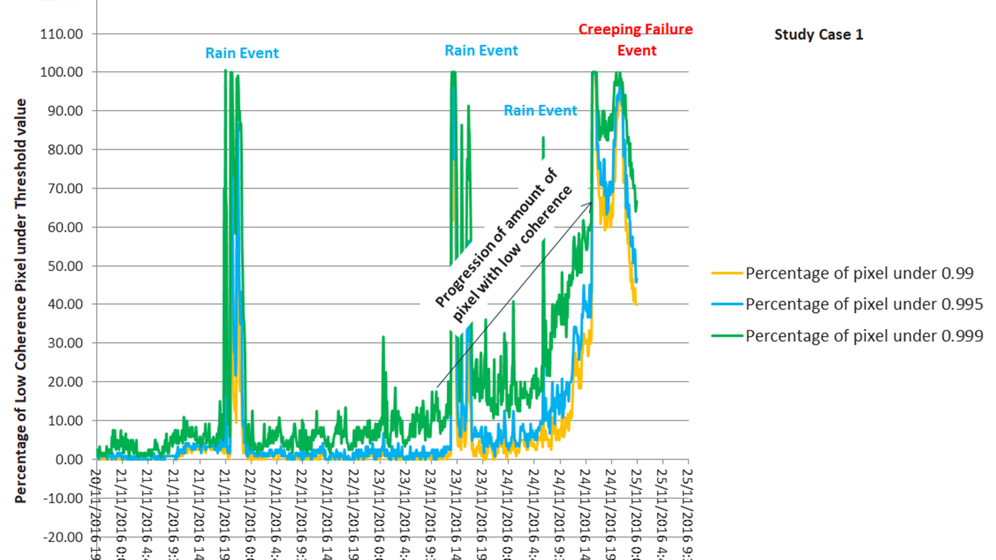
Figure 2: Coherence shifting graphic from ground-based slope radar study case 1
To enhance the ability to detect impending failure utilising the coherence-shifting method, an alarm system is implemented with several settings. The alarm back-analysis of the case study one shows a reasonable amount of warning time across the different settings of coherence threshold. The back-analysis revealed that the recommended setting of alarm is using the 0.995 value as the coherence threshold, and at this setting over 25, 50, and 75% of the total pixels underwent progressive deformation behaviour. The warning times varied from 0.8, 4.7, and 8.3 hours, and were deemed ample to conduct mitigation measures.
Case Study Two – Rapid Deformation
Case study two illustrates creeping failure, in which the rate of deformation is too fast for the ground-based slope radar to track. Despite this, the failure event in this case is still easily detected by coherence, with the coherence image becoming progressively darker over time. However, using the progressive deformation method on its own will draw an incorrect conclusion about when the failure will occur. As the ambiguity happens, the chart of deformation from ground-based slope radar becomes less reliable as the radar has already lost track of wall deformation, which could suggest the failure has already occurred By using coherence analysis, it is clear that the deformation process is actually still developing, even after the ambiguity. The coherence-shifting graphic in this case depicts a visible progression from high to low coherence (Figure 3).
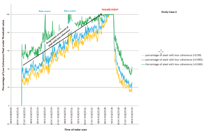
Figure 3: Coherence shifting graphic from ground-based radar
The alarm back-analysis shows that the coherence shifting did not represent a whole failure sequence from beginning to end because the start of the radar scan for this case is already halfway of the progressive deformation behaviour. Using 25% of total pixels produces the same results across three coherence thresholds. This result also suggests that the nature of the failure mechanism belongs to the creeping type, the coherence shifting tends to take a longer time before reaching the full percentage of coherence pixel deflation. The result from the alarm-back analysis suggests that the best possible coherence threshold to be applied is 0.990, yielding warning times at 16, 40, and 63 hours prior to failure.
Case Study Three – Mining Failure with Typical Hard Rock
Case study three takes place in a mining area with a typical hard rock system, which will affect how coherence shifting develops. Failures in hard rock systems, like those encountered in gold and diamond mines, are typically preceded by short-term progressive deformation. In this example, the coherence image shifting from light to dark inwardly signifies a failure influenced by a geological structure. The coherence-shifting graphic showed a progression curve of the pixel percentage, with the coherence value remaining below the threshold as the radar scan time progressed (Figure 4).
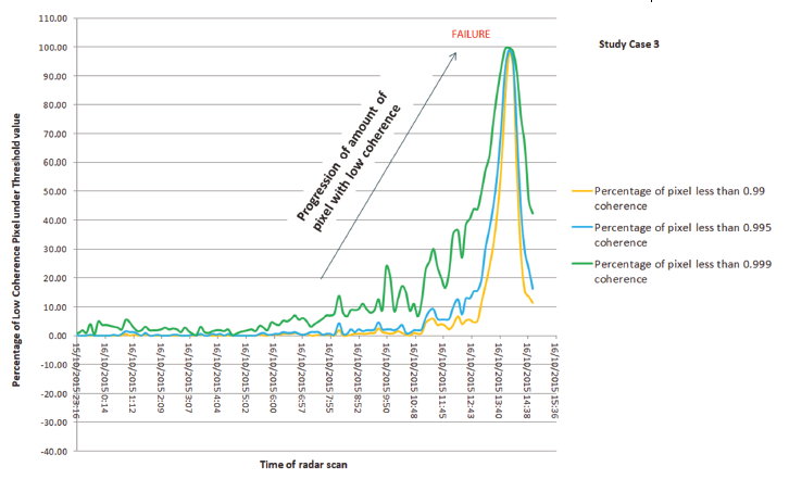
Figure 4: Coherence shifting graphic from ground-based radar
This case is an example of a hard rock system where the coherence shifting tends to progress in a more rapid fashion than the case in a soft rock system. Hence for this case, a different alarm setting is introduced, with the amount of pixels for the alarm to be triggered at 15, 25 and 50% of the total pixels experiencing progressive deformation behaviour. The result from the alarm back-analysis suggests that the best possible coherence threshold to be applied is 0.999, which will yield warning times at 0.7, 2.5 and 2.7 hours prior to failure.
Application, Limitations and Conclusion
By applying the coherence-shifting method in conjunction with an alarm system, the detection of an impending failure could be greatly enhanced. As the case studies show, warning notifications varied from 0.7 hours to more than 12 hours, providing ample time for a range of mitigation measures to be implemented. However, this new method for detecting impending failure inherently relies on other conventional methods, including detecting failure by observing its progressive deformation behaviour. The most critical factor is the understanding of the person analysing the radar data and their ability to recognise the limitations of coherence. Notwithstanding its limitations, detection with the coherence shifting method could provide enormous help to mining industry slope stability programs that deploy ground-based slope radar as its monitoring tool.
Read More
This article is a summary of the paper New approach to detect imminent slope failure by utilising coherence attribute measurement on ground-based slope radar by RH Musa, R Dwitya and FA Cahyo. The paper was presented at the 2020 International Symposium on Slope Stability in Open Pit Mining and Civil Engineering on May 12, 2020.