DIGITAL SOLUTIONS
MEMS Digital In-place Inclinometer System
RST’s new, MEMS Digital In-Place Inclinometer (IPI) System is designed to reliably measure lateral movement in and around dams, embankments, landfills, landslides, piles, piers, retaining walls, and abutments, particularly when continuous remote monitoring is required. It provides an early warning for movements, essential for protecting life and equipment.
Overview
Overview
MEMS Digital In-Place Inclinometer (IPI) Systems are designed to measure lateral movement when remote and continuous monitoring is required.
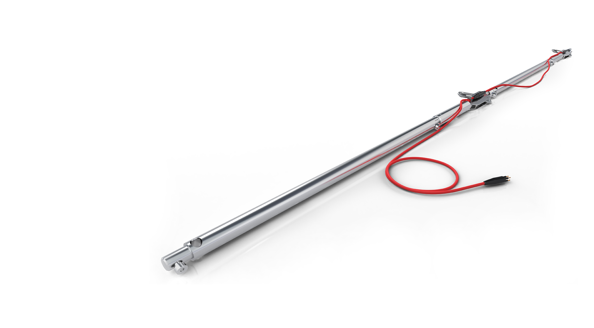
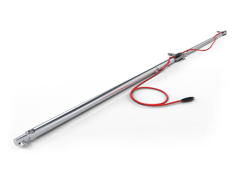
Horizontal IPI sensors are also available for vertical deformation applications as well as inclined versions upon request. Each IPI employs MEMS accelerometer sensors housed inside a 28.1 mm (1.125 in) diameter, water-tight, stainless steel enclosure. The sensor body is rigidly connected to a 25.4 mm (1.0 in) diameter bay rod which establishes the length of the IPI. Multiple IPIs are assembled with pivots allowing sensing of displacement over discreet, configurable intervals. Wheel assemblies centralize the pivot point and establish the azimuth of each IPI. They are available in sizes to fit 70 mm (2.75 in) or 85 mm (3.34 in) OD inclinometer casing. The sensors are read through a connectorized signal cable which chains together multiple sensors. A data logger is used to monitor the deflection of each sensor on the digital bus. If necessary, an alarm can be triggered when movement reaches a threshold rate or magnitude.
Product features
- Up to 70% reduction in installation time compared to previous generation
- IP68 (2 MPa), stainless steel enclosure
- Wet-mate submersible connector
- Precision locking & tools free bay rod connections
Benefits
Benefits
Data insights
Ease of use
Improve safety
Features and benefits
Features and benefits
MEMS Digital In-Place Inclinometer Sensor Specifications
| Range | ± 30° |
| Resolution | 0.0002° (0.004 mm/m) |
| Sensor Precision | ± 0.0013° (0.02 mm/m)1 ± 0.0005° (0.01 mm/m)2 |
| Sensor 24 h Stability | ± 0.03° mm/m1 ± 0.01° mm/m2 |
| System Precision | ± 0.5 mm for 30 m IPI (15 sensors @ 2 m, 6 months, repeatability conditions in borehole) |
| Sensor | MEMS (Micro-Electro-Mechanical Systems) Accelerometer |
| Temperature Dependent Uncertainty | ± 0.016 mm/m/°C (±0.001°/°C) , for ± 5° from vertical ± 0.033 mm/m/°C (±0.002°/°C) , for ± 15° from vertical |
| Temperature Accuracy | ± 0.5 °C (0°C to 60°C) ± 1.0 °C (-40°C to 60°C) |
| Temperature Resolution | 0.06°C |
Electrical Specifications
| Supply Voltage | 5 to 15V DC |
| Operating Current | 490 uA (Reading Average, per sensor) |
| Standby Current | <20uA (per sensor) |
| Signal Output | RS485 Digital Bus (MODBUS RTU Protocol) |
| Operating Temp. | -40 to 60°C (-40 to 140°F) |
Mechanical Specifications
| Ingress Protection | IP68 (2 MPa) |
| Gauge Length | 0.5 to 3 m |
| Sensor Diameter | 28.6 mm (1.125 in) |
| Bay Rod Diameter | 25.4 mm (1.0 in) |
| Wheel Assembly | 70 mm (2.75 in) 85 mm (3.34 in) |
| System Maximum Weight | 180 kgf |
| Sensor & Bay Rod Assembly Weight (dry, submerged H20) | 0.5m: 1.25, 1.00 kgf 1.0m: 1.63, 1.12 kgf 1.5m: 2.00, 1.24 kgf 2.0m: 2.37, 1.36 kgf 3.0m: 3.11, 1.60 kgf |
1:99% Confidence Interval, 2:68% Confidence Interval
Resources
Resources
Industries
Industries
Civil infrastructure
Energy
Surface metal
Underground mining
Related products

Digital Solutions
Digital Vertical Inclinometer System

Digital Solutions
Digital Inclinometer Spiral Sensor

Digital Solutions
Digital Horizontal Inclinometer System

Digital Solutions
Metallic Time Domain Reflectometry (TDR)

Digital Solutions
Inclinometer Casing
RST Instruments range

Digital Solutions
RSTAR Affinity

Digital Solutions
Data Loggers

Digital Solutions
Software

Digital Solutions
Piezometers

Digital Solutions
Inclinometers

Digital Solutions
Tiltmeters

Digital Solutions
Settlement Systems

Digital Solutions
Extensometers

Digital Solutions
Crack Meters

Digital Solutions
Strain Gauges and Strain Meters

Digital Solutions
Pressure Cells

Digital Solutions
Load Cells

Digital Solutions
Thermistors

Digital Solutions
Signal Cables

Digital Solutions
Readouts

Digital Solutions
Service and Partners
Explore more
We are a global leader in geotechnical, geospatial and structural monitoring. We deliver a complete portfolio, from sensors to services, for mining and civil infrastructure customers. Our expertise is grounded in Orica's innovation and technical excellence that span more than 150 years.

Contact an expert
Contact an expert